

![Spectracom Securesync 1204-04 ASCII Time Code I/O RS-485 Expansion Option Card [Used]-www.prostudioconnection.com](http://prostudioconnection.com/cdn/shop/files/57_da9bc757-5fd9-4316-a67f-c29a42491451_{width}x.jpg?v=1755886309)
![Spectracom Securesync 1204-04 ASCII Time Code I/O RS-485 Expansion Option Card [Used]-www.prostudioconnection.com](http://prostudioconnection.com/cdn/shop/files/57_3d654e03-87ae-4a92-8819-5b6522029fcf_{width}x.jpg?v=1755886309)
![Spectracom Securesync 1204-04 ASCII Time Code I/O RS-485 Expansion Option Card [Used]-www.prostudioconnection.com](http://prostudioconnection.com/cdn/shop/files/57_e70b6f32-bbab-4938-8661-b7900daa36b5_{width}x.jpg?v=1755886309)
![Spectracom Securesync 1204-04 ASCII Time Code I/O RS-485 Expansion Option Card [Used]-www.prostudioconnection.com](http://prostudioconnection.com/cdn/shop/files/57_57a49c98-6943-4e8f-989f-3ad4c5d30e98_{width}x.jpg?v=1755886309)
![Spectracom Securesync 1204-04 ASCII Time Code I/O RS-485 Expansion Option Card [Used]-www.prostudioconnection.com](http://prostudioconnection.com/cdn/shop/files/57_da9bc757-5fd9-4316-a67f-c29a42491451_1024x1024@2x.jpg?v=1755886309)
![Spectracom Securesync 1204-04 ASCII Time Code I/O RS-485 Expansion Option Card [Used]-www.prostudioconnection.com](http://prostudioconnection.com/cdn/shop/files/57_da9bc757-5fd9-4316-a67f-c29a42491451_1024x1024.jpg?v=1755886309)
![Spectracom Securesync 1204-04 ASCII Time Code I/O RS-485 Expansion Option Card [Used]-www.prostudioconnection.com](http://prostudioconnection.com/cdn/shop/files/57_3d654e03-87ae-4a92-8819-5b6522029fcf_1024x1024.jpg?v=1755886309)
![Spectracom Securesync 1204-04 ASCII Time Code I/O RS-485 Expansion Option Card [Used]-www.prostudioconnection.com](http://prostudioconnection.com/cdn/shop/files/57_e70b6f32-bbab-4938-8661-b7900daa36b5_1024x1024.jpg?v=1755886309)
![Spectracom Securesync 1204-04 ASCII Time Code I/O RS-485 Expansion Option Card [Used]-www.prostudioconnection.com](http://prostudioconnection.com/cdn/shop/files/57_57a49c98-6943-4e8f-989f-3ad4c5d30e98_1024x1024.jpg?v=1755886309)
Spectracom Securesync 1204-04 ASCII Time Code I/O RS-485 Expansion Option Card [Used]
( 286329363643) )
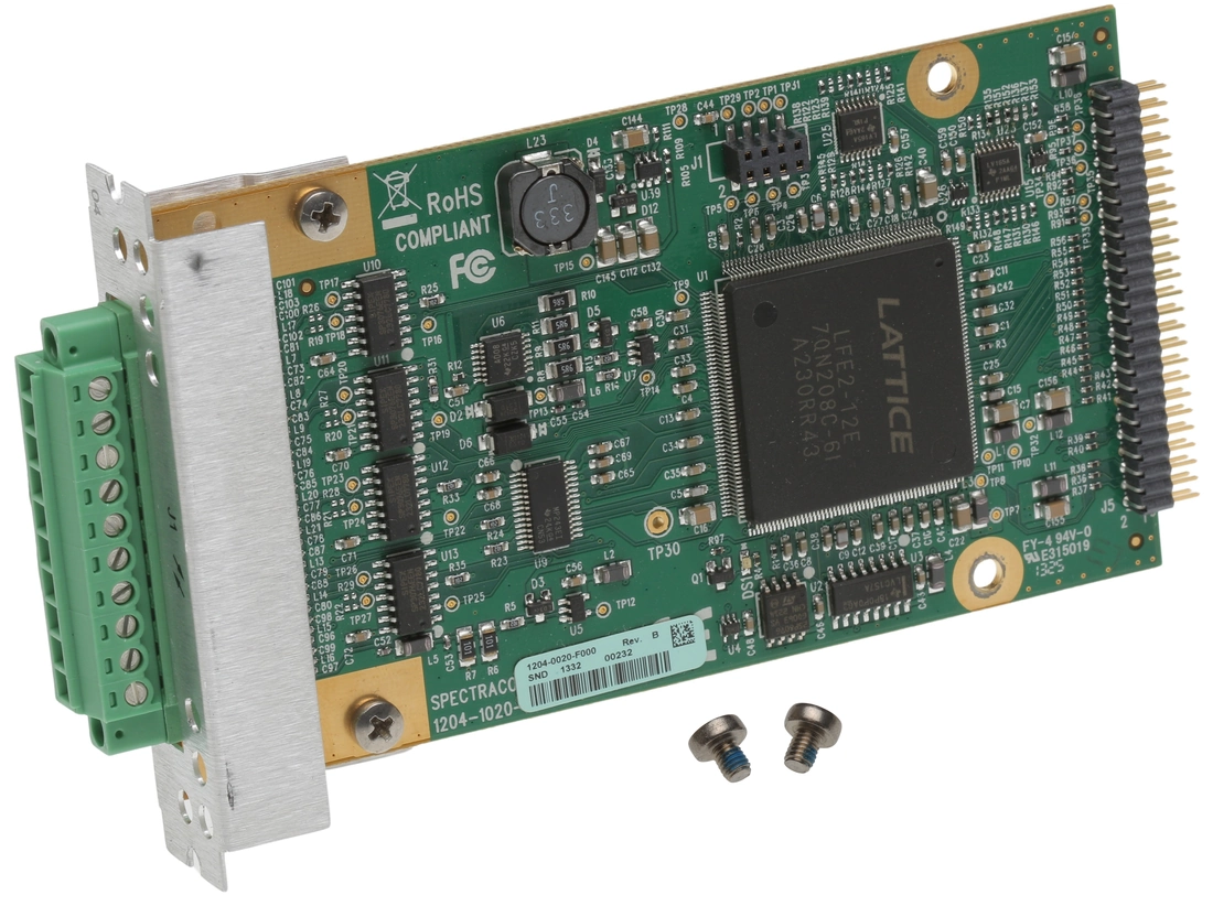
Orolia Spectracom • Part Number 1204-04 • ASCII Time Code I/O RS-485 Expansion Option Card
Description
SecureSync Option Card with (1) ASCII Time
Code Input and (1) ASCII Time Code Output [RS-485]. Limit 6 per
system.
ASCII Time Code In/Out [1204-02, -04]
The ASCII Time Code Option Card, Model 1204-02 (RS-232)
provides:
- one male DB-9 RS-232 input
connector (J2),
- and one female DB-9 RS-232
output connector (J1)
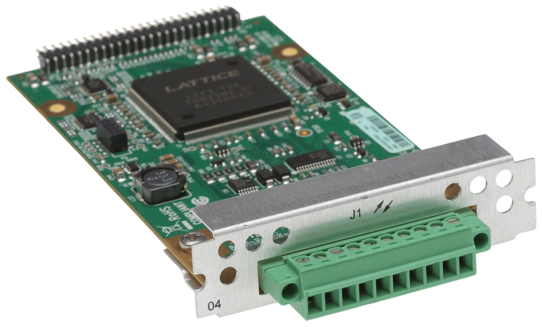
The ASCII Time Code Option Card, Model 1204-04 (RS-485)
consists
of one RS-485 input, and one RS-485 output, integrated in a
shared terminal block connector.
The interfaces accept Asynchronous Serial signals
including date and time information. The input and output Data
Formats are selected among predefined formats.
ASCII input
The ASCII input provides a serial data interface
between an ASCII time generator (e.g., another SecureSync unit),
serving
as an input reference for Time and 1PPS in order to
synchronize SecureSync (in
conjunction with, or in lieu of, other available inputs, such
as
GNSS and/or IRIG).
ASCII output
The ASCII output provides SecureSync with
the
ability to output one, two or three back-to-back ASCII time
code data streams that can be provided to peripheral devices
which accept an ASCII RS-232 input data stream for either
their
external time synchronization or for data processing. See
Time
Code
Data Formats for a description of
all supported time code formats.
The RX signal on an output
interface is used for triggering the output ASCII message
output
when a configured character is received from the peripheral
device.
When SecureSync is configured
to output only one format message (the second and third
formats
configured as “None"), the one configured message will be
available on the output port as either a broadcast message or
only upon a request character being received. SecureSync has
the
ability to output one or two additional data stream messages
immediately following the first message. In this
configuration,
only the first message determines the on-time point for the
entire output string. The on-time points for the second and
third messages that are provided at the same time as the first
message are discarded. This unique capability allows SecureSync to
be
able to simultaneously provide multiple pieces of data from
different selected format messages.
An example of selecting multiple formats is selecting
“NMEA GGA" as the first format, “NMEA RMC" as the second
format
and “NMEA ZDA" as the third format. Depending on the setting
of
the “Mode" field (which determines if the data streams are
available every second or upon a request character being
received), at the next second or the receipt of the next
request
character, the output port will provide the GGA message
followed
immediately by the corresponding RMC message for that same
second, followed immediately by the corresponding ZDA message
for that same second. The first GGA message will provide the
on-time point for the entire output data stream.
ASCII Time Code, RS-232 [1204-02]: Specifications
-
Inputs/Outputs: (1) Input, (1)
Output
-
Signal Type and Connector:
-
Connector J1 —
(RS-232 Output) RS-232 DB-9 F
-
Connector J2 –-
(RS-232 Input) RS-232 DB-9 M
-
Accuracy: ±100…1000 µs (format
dependent)
-
Maximum Number of Cards: 6
-
Ordering Information: 1204-02:
ASCII
Time Code Module (RS-232)

Model 1204-02 option
card
rear plate
Pin Assignments: OUTPUT connector J1

OUTPUT connector J1
Pin-out,
OUTPUT
connector "J1"
Pin Assignments: INPUT connector J2

INPUT connector J2
Pin-out,
INPUT
connector "J2"
ASCII Time Code, RS-485 [1204-04]: Specifications
-
Inputs/Outputs: (1) Input, (1)
Output
-
Signal Type and Connector: (1)
RS-485
terminal block for both Input and Output
-
Accuracy: ±100…1000 µs (format
dependent)
-
Maximum Number of Cards: 6
-
Ordering Information: 1204-04
ASCII
Time Code Module (RS-485)

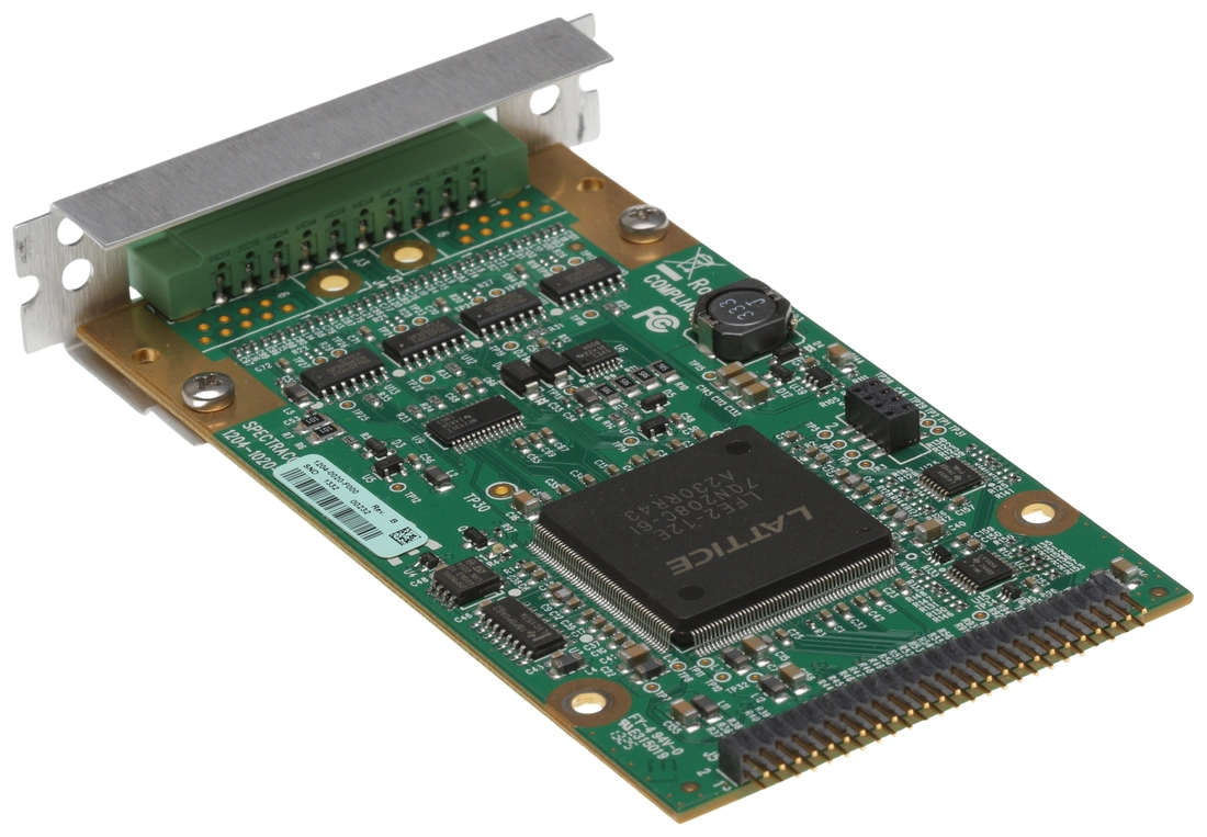
Model 1204-04 option
card
rear plate
Pin Assignments
Pin-out,
RS-485
terminal block connector J1
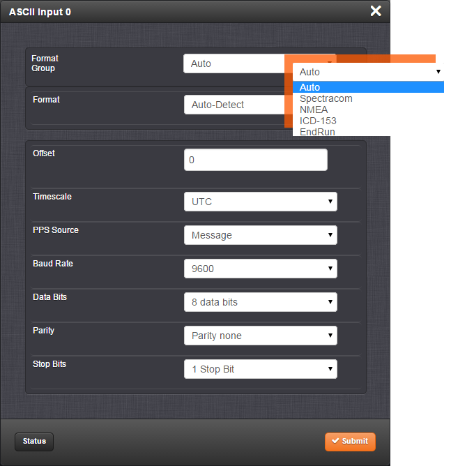
ASCII
Time Code Input: Edit Window
To configure the ASCII Input (also
referred
to as ‘Reference’), go to its Edit window.
For
instructions, see: Configuring
Option
Card Inputs/Outputs.
The Web UI list entries for this card are: ASCII TIMECODE RS-232
and ASCII TIMECODE RS-485.
Note: SecureSync starts
numbering
I/O ports with 0 (only 1PPS and 10 MHz outputs
start at 1, because of the built-in outputs).

The Input Edit window allows the configuration of
the
following settings:
-
Format Group: Determines the time
code
message format category (see also Time
Code
Data Formats.) Choices are:
- Auto
- Spectracom
- NMEA
- ICD-153
- EndRun
-
Format: Once a Format Group has
been
selected, one or more Format fields
may
appear, allowing you to select one or more time code
Formats. For detailed
specifications and limitations on the supported time code
formats, see Time
Code
Data Formats.
Note: If
Auto
is chosen as the format group, the format will
automatically be Auto-detect. SecureSync will
attempt
to identify the format of the incoming ASCII message.
-
Offset: Provides the ability to
account for ASCII input cable delays or other latencies in
the
ASCII input. The Offset value is entered and displayed in
nanoseconds (ns). The available Offset range is –500 to
+500
ms.
-
Timescale: Used to select the time
base for the incoming ASCII time code data. The entered
Timescale is used by the system to convert the time in the
incoming ASCII data stream to UTC time for use by the
System
Time. The available choices are:
-
UTC: Coordinated Universal
Time
("temps universel coordonné"), also referred to as
ZULU
time
-
TAI: Temps Atomique
International
-
GPS: The raw GPS time as
transmitted by the GNSS satellites (as of -, this is
18
seconds
ahead of UTC time)
- A local clock
set
up through the Time Management Page: This option will
appear under the name of the local clock you have set
up.
Refer to The
Time
Management Screen for more
information on how to configure and read the System
Time.
Local timescale allows a Local Clock to apply a time
offset for Time Zone and DST correction.
The incoming
input
time information may be provided as local time, but
System Time may be configured as UTC time, so
internal
computations need to be performed. With the
Timescale
field set to “Local", select the name of a
previously
created Local Clock. The Time Zone and DST rules, as
configured in the Local Clock will be applied to the
front panel time display. See for more information
on
Local Clocks.
Note: The
Timescale
of the ASCII input (as configured in the ASCII
time source) must be set correctly, especially if other
input references are enabled. Failure to configure the
Timescale of the ASCII input correctly could result in
time
jumps occurring in the System Time when input reference
changes occur. These time jumps could affect NTP and
normal
operation of the system.
-
PPS Source – choices
are:
-
Message: The 1PPS on time
point is
extracted from the ASCII message received.
-
1PPS Pin: The origin of the
1PPS
on-time-point is the 1PPS input connector.
-
Baud Rate: Determines the speed at
which the input port will operate.
-
Data Bits: Defines the number of
Data
Bits for the input output.
-
Parity: Configures the parity
checking
of the input port.
-
Stop Bits: Defines the number of
Stop
Bits for the input port.
ASCII Time Code Output: Edit Window
To configure the ASCII Output, go to its
Edit window. For instructions, see: Configuring
Option
Card Inputs/Outputs.
The Web UI list entries for this card are: ASCII TIMECODE RS-232
and ASCII TIMECODE RS-485.
Note: SecureSync starts
numbering
I/O ports with 0 (only 1PPS and 10 MHz outputs
start at 1, because of the built-in outputs). .

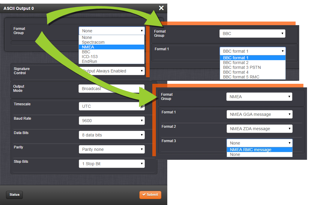
The Output Edit window allows the configuration of
the
following settings:
-
Format Group –
configures the message format type. Choices are:
- None (no message will
be
output)
- Spectracom
- NMEA
- BBC
- ICD-153
- EndRun
Once selected, the
Format Group
may
offer a choice of Formats. For more information on
supported Formats, see Time
Code
Data Formats.
-
Format 1: Selects either the
first
of up to three, or the only format message to be
output.
-
Format 2: Selects the second
consecutive format message to be outputted. Select
“None"
if only one output format is desired. “None" will be
the
only choice available if Format 1 is “None."
-
Format 3: Selects the third
consecutive format message to be outputted. Select
“None"
if only one output format is desired. “None" will be
the
only choice available if Format 2 is “None."
-
Signature Control: Signature
Control
controls when the selected ASCII data output format will
be
present; see Signature
Control.
-
Output Mode: This field determines
when the output data will be provided. The available Mode
selections are as follows:
-
Broadcast: The format messages
are
automatically sent out on authorized condition
(Signature
control), every second a message is generated in sync
with
the 1PPS.
-
Request (On-time): A format
message is generated in sync with 1PPS after the
configured request character has been received.
-
Request (Immediate): A format
message is generated as soon as the request character
is
received. As this selection does not correlate the
output
data to the on-time point for the message, in Data
Formats
that do not provide sub-second information (such as
Formats 0 and 1 whereas Format 2 provides sub-second
information), it should be noted that the output data
can
be provided immediately, but a time error could occur
when
using the on-time point of the message in addition to
the
data for timing applications.
-
Note: The
choices
available in this field are determined by the
choices of Format Group and Format.
-
Time Scale: Used to select the
time
base for the incoming data. The entered Timescale is used
by
the system to convert the time in the incoming data stream
to
UTC time for use by the System Time. The available choices
are:
-
UTC: Coordinated Universal
Time
("temps universel coordonné"), also referred to as
ZULU
time
-
TAI: Temps Atomique
International
-
GPS: The raw GPS time as
transmitted by the GNSS satellites (as of -, this is
currently 18 seconds ahead of
UTC time).
If GPS or TAI time
is
used, then the proper timescale offsets must be set on
the MANAGEMENT/OTHER/Time
Management page. (See The
Time
Management Screen for more
information on how to configure and read the System
Time).
Local timescale allows a Local Clock to apply a time
offset
for Time Zone and DST correction.
- A Local Clock
can
be set up through the Time
Management page:
This option will appear under the name of the local
clock
you have set up. See for more information. Local
timescale
allows a Local Clock to apply a time offset for Time
Zone
and DST correction.
The incoming
input
time information may be provided as local time, but
System Time may be configured as UTC time, so
internal
computations need to be performed. With the
Timescale
field set to “Local", select the name of a
previously
created Local Clock. The Time Zone and DST rules, as
configured in the Local Clock will be applied to the
front panel time display. See for more information
on
Local Clocks.
-
Baud Rate: Determines the speed at
which the output port will operate.
-
Data Bits: Defines the number of
Data
Bits for the output port.
-
Parity: Configures the parity
checking
of the output port.
-
Stop Bits: Defines the number of
Stop
Bits for the output.
ASCII Time Code Output: Status Window
To view the current settings of the ASCII Output, go to its
Status window. For instructions, see: Viewing
Input/Output
Configuration Settings.
The Web UI list entries for this card are: ASCII TIMECODE RS-232
and ASCII TIMECODE RS-485.
Note: SecureSync starts
numbering
I/O ports with 0 (only 1PPS and 10 MHz outputs
start at 1, because of the built-in outputs).

The Status window displays the following settings:
-
Signature Control: Indicates
whether
Signature Control is enabled (Signature Control determines
when the ASCII data stream will be enabled to be present).
See
also: Signature
Control.
-
Format 1: Indicates the configured
format of the ASCII time code input data stream.
-
Format 2: Indicates the configured
format of the second consecutive ASCII time code input
data
stream.
-
Format 3: Indicates the configured
format of the third consecutive ASCII time code input data
stream.
- Connector J1 — (RS-232 Output) RS-232 DB-9 F
- Connector J2 –- (RS-232 Input) RS-232 DB-9 M


- Auto
- Spectracom
- NMEA
- ICD-153
- EndRun
- UTC: Coordinated Universal Time ("temps universel coordonné"), also referred to as ZULU time
- TAI: Temps Atomique International
- GPS: The raw GPS time as transmitted by the GNSS satellites (as of -, this is 18 seconds ahead of UTC time)
- A local clock
set
up through the Time Management Page: This option will
appear under the name of the local clock you have set
up.
Refer to The
Time
Management Screen for more
information on how to configure and read the System
Time.
Local timescale allows a Local Clock to apply a time
offset for Time Zone and DST correction.
The incoming input time information may be provided as local time, but System Time may be configured as UTC time, so internal computations need to be performed. With the Timescale field set to “Local", select the name of a previously created Local Clock. The Time Zone and DST rules, as configured in the Local Clock will be applied to the front panel time display. See for more information on Local Clocks.
Note: The Timescale of the ASCII input (as configured in the ASCII time source) must be set correctly, especially if other input references are enabled. Failure to configure the Timescale of the ASCII input correctly could result in time jumps occurring in the System Time when input reference changes occur. These time jumps could affect NTP and normal operation of the system.
- Message: The 1PPS on time point is extracted from the ASCII message received.
- 1PPS Pin: The origin of the 1PPS on-time-point is the 1PPS input connector.
- None (no message will be output)
- Spectracom
- NMEA
- BBC
- ICD-153
- EndRun
Once selected, the Format Group may offer a choice of Formats. For more information on supported Formats, see Time Code Data Formats.
- Format 1: Selects either the first of up to three, or the only format message to be output.
- Format 2: Selects the second consecutive format message to be outputted. Select “None" if only one output format is desired. “None" will be the only choice available if Format 1 is “None."
- Format 3: Selects the third consecutive format message to be outputted. Select “None" if only one output format is desired. “None" will be the only choice available if Format 2 is “None."
- Broadcast: The format messages are automatically sent out on authorized condition (Signature control), every second a message is generated in sync with the 1PPS.
- Request (On-time): A format message is generated in sync with 1PPS after the configured request character has been received.
- Request (Immediate): A format message is generated as soon as the request character is received. As this selection does not correlate the output data to the on-time point for the message, in Data Formats that do not provide sub-second information (such as Formats 0 and 1 whereas Format 2 provides sub-second information), it should be noted that the output data can be provided immediately, but a time error could occur when using the on-time point of the message in addition to the data for timing applications.
-
Note: The choices available in this field are determined by the choices of Format Group and Format.
- UTC: Coordinated Universal Time ("temps universel coordonné"), also referred to as ZULU time
- TAI: Temps Atomique International
- GPS: The raw GPS time as transmitted by the GNSS satellites (as of -, this is currently 18 seconds ahead of UTC time).
If GPS or TAI time is used, then the proper timescale offsets must be set on the MANAGEMENT/OTHER/Time Management page. (See The Time Management Screen for more information on how to configure and read the System Time). Local timescale allows a Local Clock to apply a time offset for Time Zone and DST correction.
- A Local Clock
can
be set up through the Time
Management page:
This option will appear under the name of the local
clock
you have set up. See for more information. Local
timescale
allows a Local Clock to apply a time offset for Time
Zone
and DST correction.
The incoming input time information may be provided as local time, but System Time may be configured as UTC time, so internal computations need to be performed. With the Timescale field set to “Local", select the name of a previously created Local Clock. The Time Zone and DST rules, as configured in the Local Clock will be applied to the front panel time display. See for more information on Local Clocks.

ASCII Time Code Input: Status Window
To view the current settings
of the ASCII Input (also
referred to as ‘Reference’), go to its Status window. For
instructions, see: Viewing
Input/Output
Configuration Settings.
The Web UI list entries for this card are: ASCII TIMECODE RS-232
and ASCII TIMECODE RS-485.
Note: SecureSync starts
numbering
I/O ports with 0 (only 1PPS and 10 MHz outputs
start at 1, because of the built-in outputs).

The Status window displays the following settings:
-
Reference ID: Indicates the
letters
used in the Input Reference Priority table for this
particular
input reference.
-
Validity: Indicates whether
the
ASCII input data is present and considered valid for
Time
and 1PPS references.
- A green
light
indicates a valid reference.
- An orange
light
indicates the reference is not considered valid.
-
Leap Flag: Displays whether the
incoming data stream is indicating that a pending leap
second
is to be added to the UTC timescale at the end of the
month.
See Leap
Seconds.
-
Format: Indicates the configured
format of the ASCII time code input data stream.

-
Validity: Indicates whether
the
ASCII input data is present and considered valid for
Time
and 1PPS references.
- A green light indicates a valid reference.
- An orange light indicates the reference is not considered valid.
![GPS Receiver Card Motorola M12+ Furuno GT-8031 Pentar SA101 /Good TIME Bad DATE [Used]-www.prostudioconnection.com](http://prostudioconnection.com/cdn/shop/files/57_682eb0c5-91b0-4559-be8c-da1d050bfe06_{width}x.jpg?v=1755812108)
![GPS Receiver Card Motorola M12+ Furuno GT-8031 Pentar SA101 /Good TIME Bad DATE [Used]-www.prostudioconnection.com](http://prostudioconnection.com/cdn/shop/files/57_682eb0c5-91b0-4559-be8c-da1d050bfe06_large.jpg?v=1755812108)


